Call us now
07971191854
Call us now
07971191854
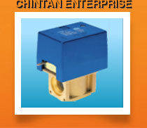
| MOTORIZED SPRING-RETURN ZONE VALVES FOR HYDRAULIC CIRCUITS |
| MAIN CHARACTERISTICS : These are powered by an electric motor and can assume two operating positions depending on whether or not the motor is activated. One two auxiliary switches can be installed and be actuated when the valve switches. Valves are equipped with a three-way SF valves. They are designed to make the connection system to plumbing pipelines more versatile. When a special flange is mounted on these valves they can be equipped with the most suitable system of connections. Various types of flanges are available and can be preassembled with the valve. These cover practically the entire range of the type of the types of connections currently in use. The flange system can also simplify, in particular cases, disconnection of the valve body form the pipeline system. |
| OPERATION: When it is without electricity the valve is positioned as in fig.1: the valve is closed. When the electrical supply is activated the motor overcomes the force of the spring and moves the bell form way A to an intermediate position in the two-way versions or closes way B in the 3-way version (fig.2). The shut- off ball remains in this position until the electrical power supply is deactivated. When the electrical power supply is deactivated the return spring brings the shut-off ball back to way A. |
| USING THE MANUAL LEVER: A lever is position next to the servomotor that permits manual positioning of the shut-off ball in an inter- mediate position (fig.3). This is useful when filling or emptying the hydraulic system. The lever reset, form manual to automatic, takes place automatically whenever the valve is activated by electricity. |
| AUXILIARY SWITCHES: A single pole micro switch (M1 version with C-NO connection), a two-pole micro switch (M1 version) or two micro switches (M2 or M2S version) can be mounted on all versions. There is a Special kit for mounting the auxiliary single-pole micro switch even in versions that do not carry it is an original part (M1 Kit). M1S kits, M2 or M2S cannot be installed on versions which do not mount them originally. |
FUNCTIONAL CHARACTERISTICS :
|
MATERIALS :
|
| APPLICATION EXAMPLE .1) INSTALLATION OF THE TWO-WAY ZONE VALVE This is the typical zone installation. It requires SF valves with travel limit micro switch to stop the pump when they are all closed. Other standard market components are also necessary such as valves with a differential by-pass to prevent bothersome noise and to keep pump pressure constant. |
| INSTALLATION OF THE THREE -WAY ZONE VALVE This is the most up-to date installation. It uses the recirculation path, duly regulated by a gate valve, to obtain good room temperature adjustments. It is also easy to install a clock to be able to subdivide operating costs. |

Price:

Price 100-300000 INR / Unit
Minimum Order Quantity : 1 Unit
Pressure : Other, Upto 1500 Pa
Valve Size : 100 mm to 500 mm
Disc : Galvanized/Aluminium/Aerofoil
Port Size : 100 mm to 500 mm (custom sizes available)
Price 100-300000 INR / Unit
Minimum Order Quantity : 1 Unit
Pressure : Other, Max 16 bar
Valve Size : DN15 to DN200
Disc : Stainless Steel
Port Size : 15 mm to 200 mm

Price 100-300000 INR / Unit
Minimum Order Quantity : 1 Unit
Pressure : Other, 16 bar (max)
Valve Size : 15mm to 100mm
Disc : Stainless steel
Port Size : DN15 to DN100
Price 100-300000 INR / Unit
Minimum Order Quantity : 1 Unit
Pressure : Other, Up to 1 MPa (10 bar)
Valve Size : 1/2 Inch
Disc : Plastic
Port Size : 1/2 Inch BSPT


|

 Send Inquiry

